- 您现在的位置:买卖IC网 > Sheet目录861 > GCM188R71E154KA37D (Murata Electronics North America)CAP CER 0.15UF 25V 10% X7R 0603
�� �
�
�!� Note� ?� Please� read� rating� and� !� CAUTION� (for� storage,� operating,� rating,� soldering,� mounting� and� handling)� in� this� catalog� to� prevent� smoking� and/or� burning,� etc.�
�?� This� catalog� has� only� typical� speci?cations.� Therefore,� please� approve� our� product� speci?cations� or� transact� the� approval� sheet� for� product� speci?cations� before� ordering.�
�!� Caution�
�Continued� from� the� preceding� page.�
�2.� Measurement� of� Capacitance�
�1.� Measure� capacitance� with� the� voltage� and� frequency�
�specified� in� the� product� specifications.�
�1-1.� The� output� voltage� of� the� measuring� equipment� may�
�decrease� occasionally� when� capacitance� is� high.�
�Please� confirm� whether� a� prescribed� measured�
�voltage� is� impressed� to� the� capacitor.�
�1-2.� The� capacitance� values� of� high� dielectric� constant�
�type� capacitors� change� depending� on� the� AC� voltage�
�applied.� Please� consider� the� AC� voltage�
�characteristics� when� selecting� a� capacitor� to� be� used�
�in� an� AC� circuit.�
�3.� Applied� Voltage�
�1.� Do� not� apply� a� voltage� to� the� capacitor� that� exceeds� the�
�rated� voltage� as� called� out� in� the� specifications.�
�1-1.� Applied� voltage� between� the� terminals� of� a� capacitor�
�shall� be� less� than� or� equal� to� the� rated� voltage.�
�(1)� When� AC� voltage� is� superimposed� on� DC� voltage,�
�the� zero-to-peak� voltage� shall� not� exceed� the�
�rated� DC� voltage.�
�When� AC� voltage� or� pulse� voltage� is� applied,� the�
�peak-to-peak� voltage� shall� not� exceed� the� rated�
�DC� voltage.�
�(2)� Abnormal� voltages� (surge� voltage,� static�
�electricity,� pulse� voltage,� etc.)� shall� not� exceed�
�the� rated� DC� voltage.�
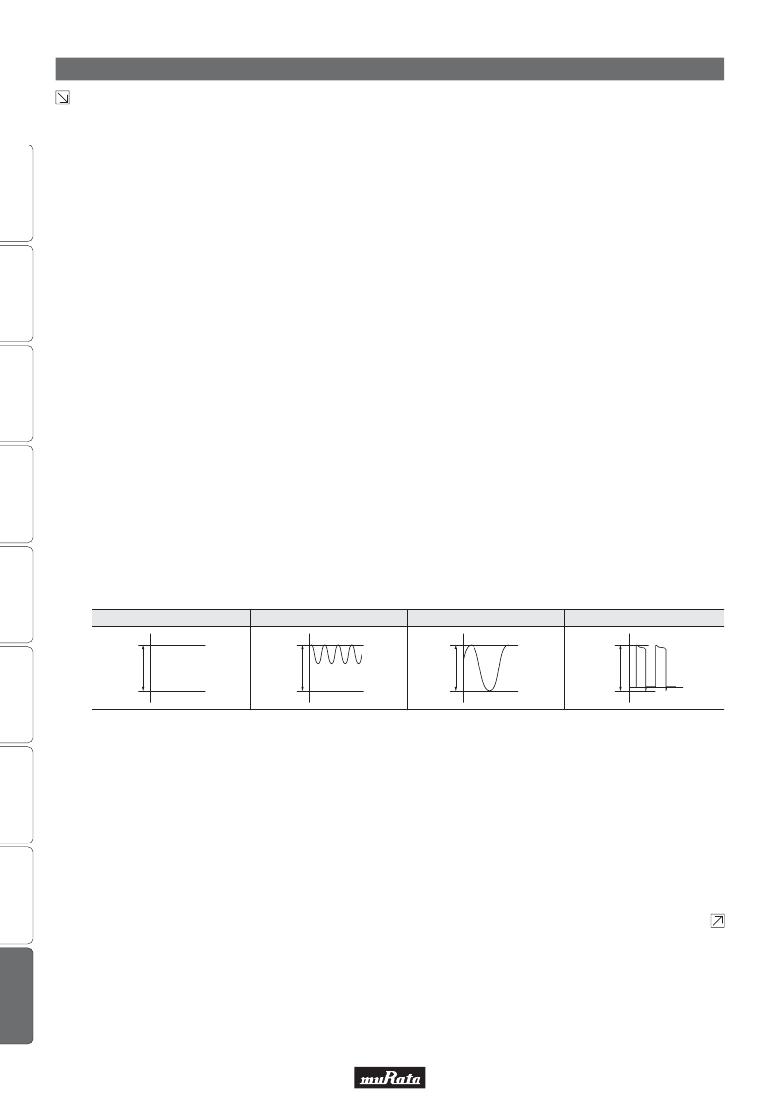
�Typical� Voltage� Applied� to� the� DC� Capacitor�
�C03E.pdf�
�May.17,2013�
�DC� Voltage�
�DC� Voltage+AC�
�AC� Voltage�
�Pulse� Voltage�
�E�
�E�
�E�
�0�
�E�
�0�
�0�
�0�
�(E:� Maximum� possible� applied� voltage.)�
�1-2.� Influence� of� over� voltage�
�Over� voltage� that� is� applied� to� the� capacitor� may�
�result� in� an� electrical� short� circuit� caused� by� the�
�breakdown� of� the� internal� dielectric� layers.�
�The� time� duration� until� breakdown� depends� on� the�
�applied� voltage� and� the� ambient� temperature.�
�2.� Use� a� safety� standard� certified� capacitor� in� a� power�
�supply� input� circuit� (AC� filter),� as� it� is� also� necessary� to�
�consider� the� withstand� voltage� and� impulse� withstand�
�voltage� defined� for� each� device.�
�Continued� on� the� following� page.�
�46�
�发布紧急采购,3分钟左右您将得到回复。
相关PDF资料
GCM31A7U2J471JX01D
CAP CER 470PF 630V 5% U2J 1206
GCM31C5C1H104JA16L
CAP CER 0.1UF 50V 5% NP0 1206
GHF459601ZA6N
CAP ARRAY 6CH 600PF 50V 1404
GL2L5LS050D-T1-C
DELAY LINE 0.5NS +-50PS 16SOIC
GL6R0KA7B200
INDUCTOR BROADBAND 6UH
GP447
CAP CER 47PF 1KV 10% RADIAL
GRF4.0419.013.C
GRF4 APPLIANCE INLET FILTER 15A
GRM022R60J332KE19D
CAP CER 3300PF 6.3V X5R 01005
相关代理商/技术参数
GCM188R71E154KA37J
功能描述:多层陶瓷电容器MLCC - SMD/SMT 0.15uF 25Volts X7R 0.1
RoHS:否 制造商:American Technical Ceramics (ATC) 电容:10 pF 容差:1 % 电压额定值:250 V 温度系数/代码:C0G (NP0) 外壳代码 - in:0505 外壳代码 - mm:1414 工作温度范围:- 55 C to + 125 C 产品:Low ESR MLCCs 封装:Reel
GCM188R71E222KA37D
功能描述:多层陶瓷电容器MLCC - SMD/SMT 0.0022uF 25Volts X7R 10%
RoHS:否 制造商:American Technical Ceramics (ATC) 电容:10 pF 容差:1 % 电压额定值:250 V 温度系数/代码:C0G (NP0) 外壳代码 - in:0505 外壳代码 - mm:1414 工作温度范围:- 55 C to + 125 C 产品:Low ESR MLCCs 封装:Reel
GCM188R71E223KA02D
功能描述:多层陶瓷电容器MLCC - SMD/SMT 0603 0.022uF 25volts X7R 10%
RoHS:否 制造商:American Technical Ceramics (ATC) 电容:10 pF 容差:1 % 电压额定值:250 V 温度系数/代码:C0G (NP0) 外壳代码 - in:0505 外壳代码 - mm:1414 工作温度范围:- 55 C to + 125 C 产品:Low ESR MLCCs 封装:Reel
GCM188R71E223KA02J
制造商:Murata Manufacturing Co Ltd 功能描述:
GCM188R71E223KA37D
功能描述:多层陶瓷电容器MLCC - SMD/SMT 0.022uF 25Volts X7R 0.1
RoHS:否 制造商:American Technical Ceramics (ATC) 电容:10 pF 容差:1 % 电压额定值:250 V 温度系数/代码:C0G (NP0) 外壳代码 - in:0505 外壳代码 - mm:1414 工作温度范围:- 55 C to + 125 C 产品:Low ESR MLCCs 封装:Reel
GCM188R71E223KA37J
功能描述:多层陶瓷电容器MLCC - SMD/SMT 0.022uF 25Volts X7R 0.1
RoHS:否 制造商:American Technical Ceramics (ATC) 电容:10 pF 容差:1 % 电压额定值:250 V 温度系数/代码:C0G (NP0) 外壳代码 - in:0505 外壳代码 - mm:1414 工作温度范围:- 55 C to + 125 C 产品:Low ESR MLCCs 封装:Reel
GCM188R71E224K
制造商:MURATA 制造商全称:Murata Manufacturing Co., Ltd. 功能描述:Chip Monolithic Ceramic Capacitor 0603 X7R 0.22μF 25V
GCM188R71E224KA55
制造商:MURATA 制造商全称:Murata Manufacturing Co., Ltd. 功能描述:Chip Monolithic Ceramic Capacitors for Automotive